


DC Servo Amplifiers
General Description
PCD's line of DC Servo Amplifiers has been designed to meet the diverse requirements of a wide variety of control systems. Typically, they are used to drive DC torque motors, servo valves, deflection coils and servo and low inertia DC motors in such applications as numerical control systems, tape drives, camera drives, instrument systems, production test stands, rate tables, etc. Two types of packaging are used: epoxy encapsulation for units rated to 600 watts and fan cooled for larger power ratings. Some special applications including those where operation at altitude is required have supplemental cooling.
The encapsulated units are noted for their compactness and offer exceptional power to volume ratios. All are suited for direct mounting on PC boards with standard 0.2 inch pin spacing. An optional mating socket is available for applications where mounting other than on a PC board is required.
All units operated as either voltage or current amplifiers. Their bandwidth is broad . . . 10 kHz for small signal, l kHz full output . . . resulting in fast response and excellent loop stability. Gain is adjustable. Short circuit protection and current limiting are included. Adjustment of the current limit is made with an external fixed or variable resistor wired into the system. Power sharing maximizes utilization of the power transistors.
All encapsulated units have a heat transfer surface for attachment to an external heat sink. The power transistors are bonded to the internal face of these surfaces to maximize heat transfer.
PCD can provide specials tailored to a specific requirement or in special shapes or configurations to meet unusual space requirements. Also, we can offer any design in a military version in compliance with the applicable requirements of MIL-STD-810, MIL-STD-1275, MIL-STD-704, and MIL-STD-461.
Figure 1
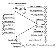
Figure 2
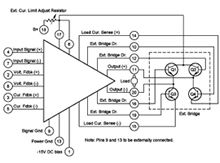
Figure 3
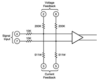
Figure 4
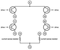
Figure 5
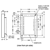
Figure 6
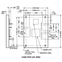
Figure 7
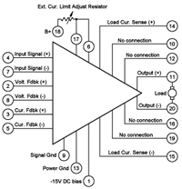
Figure 8
Technical Data PDF
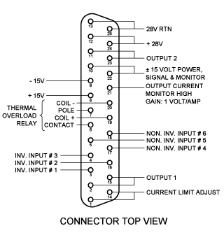
The DCA 25, DCA 25/60 and the DCA 50/60 are basically similar units differing in output ratings and physical size. The descriptive text and diagrams apply to both. The B+ input for the DCA 25 is 28VDC±3. B+ input for the DCA 25/60 and DCA50/60 is 60V DC±5. Thermal data can be found here. Terminal connections are shown in Figure 1.
The units consist of a Bridge Power Amplifier preceded by an IC Differential Amplifier of high gain and wide bandwidth. Included is a current limit loop that senses load current and prevents the load current from increasing during motor reversal and plugging to a point where it could damage the motor. The current limit loop also acts as a short circuit protection.
They also include a power sharing loop. This provides equal dissipation in both halves of the outlet bridge in the linear, current limiting and voltage saturation regions of amplifier operation.
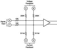
Internal Input Circuitry
The input circuitry to the differential amplifier is shown in Figure 3.
Output Bridge The output bridge circuit is shown in Figure 4:
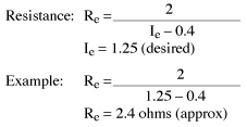
Current Limit Adjustment
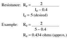
The units are internally current limited to approximately 0.4 amps.
To increase the current limit, do the following:
Connect terminal 18 (+28V DC) to terminal 17.
Place a resistor Re between terminals 6 and 17.
To determine current limit (le), select resistor as follows:
Current and Voltage Gain Adjustment
Refer to Figure 3 and 8:
Voltage Gain Increase Add equally matched resistors in series with terminals 2 and 8.
Example: 200K will double again.
Voltage Gain Decrease Add equally matched resistors in series with terminals 4 and 7. Example: 10K will halve the gain.
Current Gain Increase Add equally matched resistors in series with terminals 3 and 5. Example: 511 Ohms will double gain.
Current Gain Decrease Add equally matched resistors in series with terminals 4 and 7. Example: 10K will halve the gain.
Power Rating Power rating of resistor should be at least 2 (Ie - .4) Watts.
Null Offset Adjustment (For either voltage or current amplifier use)
Depending on polarity of offset, apply either positive or negative nulling voltage to either terminal 7, if terminal 4 is used for signal input, or to terminal 4, if terminal 7 is used for signal input. If either terminal 4 or 7 is not used, externally common the unused terminal to terminal 9.
Optional Current Or Voltage Amplifier Connections
Current Amplifier Connect terminal 14 to terminal 3, and 15 to terminal 5.
Voltage Amplifier Connect terminal 11 to terminal 8, and terminal 20 to terminal 2.
Polarity & Phasing Terminal 11 is in phase with terminal 4 and out of phase with terminal 7.
Terminal 20 is in phase with terminal 7 and out of phase with terminal 4.
Thermal Aspects
<Technical Data PDF
Amplifier parameters are valid for a mounting base temperature range of -55°C to 125°C.
The power output capacity of the DCA 25 should be carefully interpreted in relation to its internal dissipation capacity. Dissipation limits at indicated mounting base temperature are as follows:
| DCA 25 | DCA 25/60 | DCA 50/60 | |
|---|---|---|---|
| Continuous @ 25°C | 12.5W |
12.5W |
25W |
| 100 ms non-recurring | 25W |
25W |
50W |
| Derate | 0.75/°C |
0.75/°C |
0.15/°C |
Thermal resistance between free air and mounting base is 6°C/watt. Using an ATP heat radiator fastened to the mounting surface, thermal resistance is lowered to 3°C/watt.
For calculation of internal dissipation at any load current and load voltage condition use following formula:
Internal Dissipation = (Vps – V1 – 3) x (I1)
Where Vps is the magnitude of the (+) power supply voltage, V1 is the voltage drop across the load and I1 is the load current.
Application as a Bridge Amplifier
The DCA 25 or DCA 25/60 may be used as a bridge amplifier to drive a remote NPN power transistor bridge. In such an application, the DCA 25 may be mounted directly on the control card and the external bridge can be affixed to a remotely located heat sink to accommodate the required power dissipation.
Terminal connections for the DCA 25 and DCA 25/60 when used as a driver for an external bridge are shown in Figure 2. Input circuit and output circuit diagrams are shown on figures 3 to 6.
Current Limit Adjustment
The external bridge driven by a DCA 25 is load current limited to approximately 0.2 amperes. To increase the current limit, do the following:
Connect terminals 6 and 17.
Place a resistor Re between terminals 17 and 18.
Power Rating
Power rating of resistor should be at least 2 (Ie - .4) Watts.
Current and Voltage Gain Adjustment (Refer to Figure 3 or 8)
Voltage Gain Increase Add equally matched resistors in series with terminals 2 and 8. Example: 200K will double again.
Voltage Gain Decrease Add equally matched resistors in series with terminals 4 and 7. Example: 10K will halve the gain.
Current Gain Increase Add equally matched resistors in series with terminals 3 and 5. Example: 511 Ohms will double gain.
Current Gain Decrease Add equally matched resistors in series with terminals 4 and 7. Example: 10K will halve the gain.
Null Offset Adjustment (For either voltage or current amplifier use)
Depending on polarity of offset, apply either positive or negative nulling voltage to either pin 7, if terminal 4 is used for signal input, or to terminal 4, if terminal 7 is used for signal input. If either terminal 4 or 7 is not used, externally common the unused terminal to terminal 9.
Optional Current Or Voltage Amplifier Connections
Current Amplifier Connect terminal 14 to terminal 3, and 15 to terminal 5.
Voltage Amplifier Connect terminal 11 to terminal 8, and terminal 20 to terminal 2.
Polarity & Phasing Terminal 11 is in phase with terminal 4 and out of phase with terminal 5. Terminal 20 is in phase with terminal 5 and out of phase with terminal 4.
Thermal Aspects (PDF information here)
Click all figures for larger view
Figure 8
Figure 9
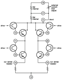
Figure 10
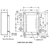
Figure 11
Technical Data PDF
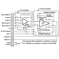
These higher rated units are identical in circuitry to the DCA 25 with the addition of an internal high-current and high-power capacity transistor bridge. In effect, the remote bridge discussed above has been incorporated as an integral part of the package. The DCA 200 and DCA 300 require a B+ supply of 28 V DC +/-3. The DCA 300/60 and DCA 600/60 require B+ of 60 V DC +/-5, while the DCA 600/100 requires 100 V DC +/-5. Thermal Data can be found here.Terminal connections are shown in Figure 7.
The input circuit is the same as that for the DCA 25 and is shown in Figure 8. Figure 9 shows the output circuit.
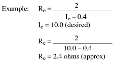
Current Limit Adjustment
The units are internally current limited to 0.2 amps. To increase the current limit, do the following:
Connect terminal 6 to terminal 17.
Place a resistor Re between terminals 17 and 18.
To determine current limit (le), select resistor as follows:
Current and Voltage Gain Adjustment (Refer to Figure 3 or 8)
Voltage Gain Increase Add equally matched resistors in series with terminals 2 and 8. Example: 200K will double again.
Voltage Gain Decrease Add equally matched resistors in series with terminals 4 and 7. Example: 10K will halve the gain.
Current Gain Increase Add equally matched resistors in series with terminals 3 and 5. Example: 511 Ohms will double gain.
Current Gain Decrease Add equally matched resistors in series with terminals 4 and 7. Example: 10K will halve the gain.
Power Rating Power rating of resistor should be at least 2 (Ie - .4) Watts.
Null Offset Adjustment (For either voltage or current amplifier use)
Depending on polarity of offset, apply either positive or negative nulling voltage to either pin 7, if terminal 4 is
used for signal input, or to terminal 4, if terminal 7 is used for signal input. If either terminal 4 or 7 is not used,
externally common the unused terminal to terminal 9.
Optional Current Or Voltage Amplifier Connections
Current Amplifier Connect terminal 14 to terminal 3, and 15 to terminal 5.
Voltage Amplifier Connect terminal 11 to terminal 8, and terminal 20 to terminal 2.
Polarity & Phasing Terminal 11 is in phase with terminal 4 and out of phase with terminal 7.
Terminal 20 is in phase with terminal 7 and out of phase with terminal 4.
Click for larger view
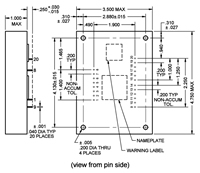
Figure 10 - Installation Dimensions
DCA 200, DCA 200/60, DCA 300 & DCA 300/60, DCA 50/2
Technical Data PDF
The DCA 50/2 is a highly reliable compact unit that contains two amplifier channels, but occupies only the board space formerly required for a single channel 25-watt unit. Similar in function to the rest of the line, the greatly reduced size of the DCA 50/2 was achieved through a number of unique innovations without sacrifice in PCD’s rigid standards. It requires a power supply of 28 V DC +/-4. Functional schematics see below. Physical dimensions are given in Figure 10. (Right)
Outline Drawing
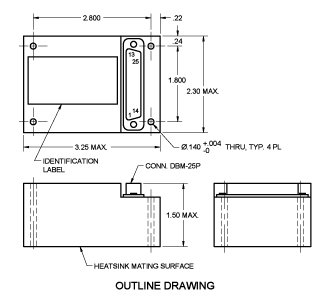
Connector Top View
PCD’s new line of encapsulated solid state servo amplifiers has extra features such as power sharing, short-circuit protection of outputs to ground, thermal-overload protection, output drive current monitor, and multiple input preamp as standard features. The units weigh only 12 ounces (340.2 grams), measure 2.29” x 3.25” x 1.5” (58.2 x 82.6 x 38.1 mm) and have a standard 25 pin connector for easy installation. A mating heat sink is available.
These highly reliable units have high open-loop gain for wide design options, wide bandwidth for fast response and loop stability, current limiting for amplifier and load protection, and voltage or current feedback for speed or torque control. Available in either standard or MIL versions.
Features:
- Power Sharing
- Short-Circuit Protection (output to ground)
- Thermal Overload Protection
- Output Drive Current Monitor
- Multiple Input Preamp
- High Open-Loop Gain
- Wide Bandwidth
- Current Limiting
- Subminiature Connector
- Available with High Reliability Parts
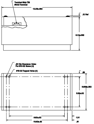
Figure 12
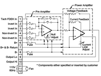
Figure 13
Technical Data PDF
ATP’s line of 0.5 kW to 1 kW Fan-cooled Linear Amplifiers has been designed specifically to meet the requirements of DC motors, particularly those with high-peak power requirements operating in control loops, and to provide flexibility for engineers with servo applications. Units, however can be supplied not only for applications requiring outputs intermediate to the ratings listed but also for other gains and other output or input voltages. Engineers having requirements not met by one of the listed units are invited to submit their specifications.
Supply and Outputs
Each size unit is available in three variations:
1. Positive and negative V DC supply of appropriate voltage, single ended output
2. Positive V DC supply of appropriate voltage and a lower level V DC negative bias, bridge output, and
3. Positive V DC supply of appropriate voltage with the required lower level negative bias provided by internal
circuitry, bridge output.
The variations are denoted by dash numbers, -1, -2, or -3, respectively. Except for these variations, units of the same model number are identical.
Construction
The units are ruggedly constructed, completely self–contained and suitable for use in portable or trailer housed equipment as well as in more usual locations. Fan-cooled, they require no external heat sinks and will dissipate full rated power at 25°C ambient without derating.
The cover is removable to provide access to the terminal strip, adjusting potentiometers, jumper for mode selection and the changing of transistors and capacitors for gain and frequency response setting.
Four #10-32 tapped holes are provided in the base for mounting.
Contact Us Today at 913.829.1900
Fax 913.829.1999 or email sales@powercontroldevices.com